Catalog
02.01.11 Test bench for electric machine winding section trials
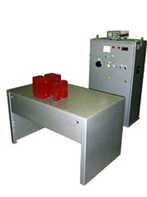
The bench is intended for electric strength trials of the main and interloop isolation of unit coils before laying winding into the stator slots. Test Bench diagram provides electric strength trials of electric machine main and interloop isolation according to GOST 183-74 Standard demands. Main isolation trial is performed by means of the testing AC regulated 2…30 kV voltage with 50 Hz frequency. Voltage measuring is taken at the secondary side of the transformer using electrostatical kilovoltmeter. The principle of Test Bench operation while testing coil isolation for electrical strength is based upon the excitation of high frequency voltage produced by electromagnetic induction at discharge of high voltage capacitor. Damage of interloop isolation in the tested coil results in excitation current in short circuited coils causing a magnetic flux in the auxiliary core inducing voltage in the measuring coil which is monitored by millivoltmeter. The main elements of the installation are: the circuit of high frequency damping oscillations, open steel core with oscillating circuit inductance, auxiliary core with measuring coil. Delivery set: -control rack; - test table; - step-up transformer IOM-50/20; -measurement transformer 3NOM-35-65E1 35/0.10 kV - oscillograff
| TECHNICAL DESCRIPTION | |
| Nominal supply voltage 50Hz, V | 380 (250A) |
| Load current, A | 100 |
| Max. operating trial voltage, | |
| - main isolation, kV | 50 |
| - coil isolation, kV/coil | 4 |
| Pulse frequency, Hz | 1-5 |
| Test bench floorspace, m2 | 11 |
| Overall dimensions:, | |
| - control rack (height/width/length), mm/mass, kg | 840x650x1500/200 |
| - test table (height/width/length), mm/mass, kg | 1300x750x770/150 |
| - step-up transformer (height/width/length), mm/mass, kg | 400x650x800/80 |
| - measurement transformer (height/width/length), mm/mass, kg | 400x500x950/40 |
| TECHNICAL DESCRIPTION OF MEASURING DEVICES: OSCILLOGRAFF S1-131: | |
| - admitted error limit, % | 5 |
| - deviation ratio on the level, mV/division | 2 – 10(4) |
| - reamer coefficient, mks/division | 0,02 – 10(7) |
| DIGITAL MEASUREMENT PFP-1: | |
| - precision rate, | 0,15 |
| - measurement speed, measurement/sec | 3 |
| - monitoring time, msec | less then 300 |
 Fig.1 Test scheme on electric stability of winding insulation according to the body 1. LATR 2. Set-up transformer 3. Measurement transformer 4. Digital voltmeter | |
 Fig. 2 Test scheme on electric stability of turn insulation 1.Set-up transformer 2. Tank capacity 3. Aerial fuse 4. Turned circuit inductance 5. Test coil 6. Coil 7. Milivometer 8. Control coil 9. Oscillograff | |
 IR - Induction regulator QS1,QS4 - end switch SI - test field pV - Kilovoltmeter TR - test transformer pS - Oscillograff SH1 - control rack test of main insulation SH2 - control rack with test turn insulation R - inductive switch (is not supplied) * - enclosed 1 - Copper wire in insulation with work voltage 0,4kV with cross-section 1,0 mm2 2 - cross-section 16 mm2 3. - In insulation with work voltage 6kV with cross section 16 mm2 |